We use cookies to make your experience better. To comply with the new e-Privacy directive, we need to ask for your consent to set the cookies. Learn more.
Free Shipping on all orders over $50*
Powering Your Eurorack System
15
Oct
Overview
At first, providing power to a Eurorack modular synthesizer system might seem daunting and complicated. But in reality, there are only a few components involved in powering a Eurorack case. First, the power supply converts wall power to low voltages that the modules can use. The second is a bus board for distributing power from the power supply to each module in the case. The last part of the chain is a ribbon cable connecting the bus board to the modules. This article will go through each of these in detail and explain the options available.Power Supply
The power supply is the first component powering a Eurorack modular system. The power supply can be built into the case internally or be an external power supply or power "brick" like a laptop uses. In both cases, the power supply's output connects to one or more bus boards. Power is then supplied to the individual modules from a bus board through multiple connectors for connecting individual modules.
In most systems, the power supply provides +12V and -12V, which are the standard power supply voltages in Eurorack systems. A +5V supply is also expected in most modern cases. Older Eurorack systems did not have +5 volt supplies because, in the earlier days of Eurorack, only a few modules required it. Therefore, if you have an older Eurorack case that does not have +5V, we offer a small add-on module that plugs into the bus board and draws from the +12V supply to provide +5V on the appropriate pins.
Another popular configuration in smaller systems is one where a power supply brick provides one voltage, like +15V, and an internal circuit converts that voltage to the +12V, -12V, and +5V needed. Some manufacturers build this additional circuitry into their bus boards. However, this configuration can quickly get expensive in larger systems because of the duplicated circuitry. In addition, having a power brick for each bus board and having wall outlets to plug them all in can be very annoying. So this is only a good idea for small cases where one power brick is enough for the entire system.
The capacity of the power supply is specified in amps for each voltage provided. The number of amps available from each power supply voltage helps determine how many modules can be powered with one power supply. However, module power consumption is usually specified in milliamps (abbreviated mA). 1000mA is equal to 1A. For example, if you have four modules that use 300mA @ +12V and 100mA @ -12V, they will use 1200mA or 1.2A of the +12V supply and 400mA of the -12V supply.
Having extra capacity available from the power supply beyond what your modules require prevents overheating the power supply and will generally reduce noise. An additional amp or two for each power supply voltage beyond what your modules need is a good practice.
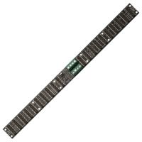
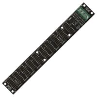
Bus Board
The next component after the power supply is the bus board. Usually, this is a circuit board mounted inside the Eurorack enclosure. The power from the power supply is usually connected with screw terminals or small connectors. In larger systems, multiple bus boards may be connected in a daisy-chain fashion. Most bus boards feature LEDs showing that the individual voltages are getting power from the power supply.
Ribbon Cables
Ribbon cables connect the individual modules to the bus board. Most bus boards have 16-pin power connectors, but Modules will either have a 16-pin or a 10-pin connector. The extra pins are for +5V, Pitch CV, and Gate CV. Most modules do not use these signals and are equipped with a 10-pin connector. These modules can be connected with a 10-pin to 16-pin ribbon cable. Most modules ship with a ribbon cable that can plug into a 16-pin bus board connector.
Parting Thoughts
Getting your Eurorack modules powered up doesn't need to be complicated. By choosing an adequate power supply, bus boards with enough connectors for the modules you will have, and having the right ribbon cables on hand, you can be sure you will get everything going the first time.
Related Products
0 Comment(s)